


Blynk is an IoT platform with customizable mobile apps, private cloud, rules engine, and device management analytics dashboard, designed for easy and customizable Internet of Things applications. Designing dashboard on Blynk App for IoT projects is really easy, you just have to organize buttons, sliders, graphs, and alternative widgets onto the screen. We can also edit the widgets as per our requirements.
With the help of Blynk, the software side gets easier than the hardware. Blynk is perfect for interfacing with simple projects like monitoring the temperature of your room or turning lights on and off remotely Here, in this project we are controlling a LED using Blynk App and Esp8266. Earlier we have controlled the LED using ESP32. So, not only with ESP8266, it’s easy to interface Blynk app with Raspberry Pi, Arduino and other microcontrollers.
Components Required
- BYNK APP (Download from Play Store)
- ESP8266 NODE MC
Blynk App Dashboard Setup for Controlling LED
To control LED with Blynk app, download and install the Blynk app from Google or Apple app store.
Then, if you are new to Blynk app, create a new account by using your Email and password.
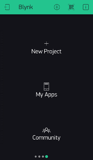
After sign up click on ‘New Project’ to start your project.
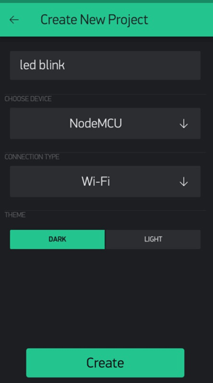
Now provide your project a name and as blynk app works with diffferent hardware models. Thus opt for your device from choices.
Here, we are using ESP8266 node MCU, so I am proceeding with node MCU. While selecting your board opt for your association sort whether or not it's Wi-Fi or LAN or USB association.
After these steps click on ‘Create’ button to form your project.
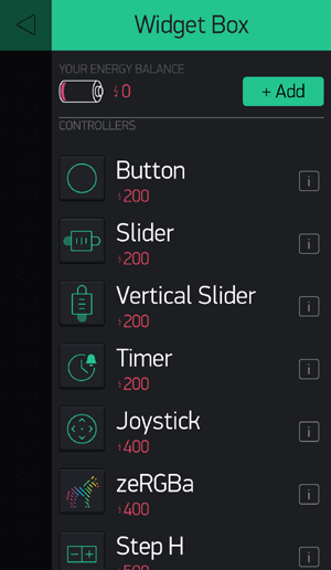
As, the blank project opens, add Widgets to it by clicking on Add button (Plus sign button)

Now after this click on ‘Button’ to add a button in your project.
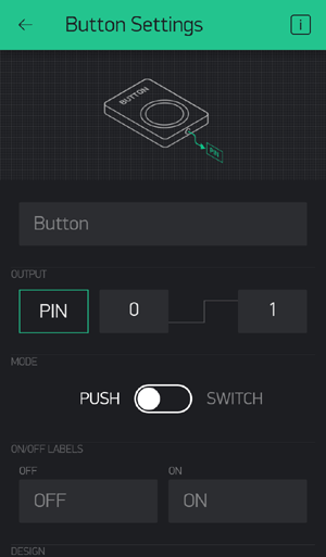
Now in button settings provide a name to your button. After assign the pin number to the ‘OUTPUT’. Also, give names to your On/Off labels.
NODE MCU Setup for Blynk App
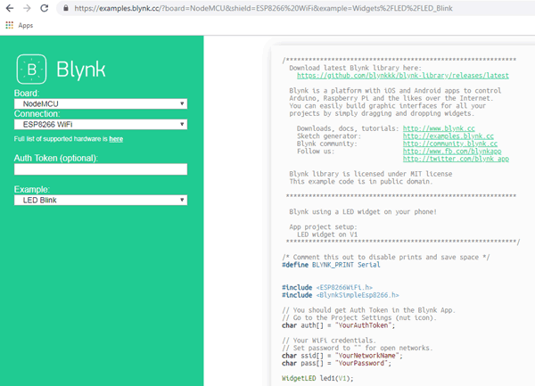
In your browser search Blynk code generator then open Blynk example browser,
Select your board and example code, as shown below:
Open Arduino IDE and select Tools option as shown below:
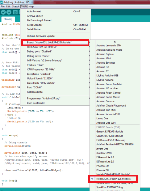
Note: You should have ESP8266 library installed in Arduino IDE.
Then copy the example code from the browser as mentioned above and paste in Arduino IDE.
Programmig Code Explanation
The complete code for Controlling LED using Blynk App and ESP8266 is given at the end. Include all the required libraries for ESP8266 and Blynk App in the code, as shown below:
#define BLYNK_PRINT Serial
#include <ESP8266WiFi.h>
#include <BlynkSimpleEsp8266.h>
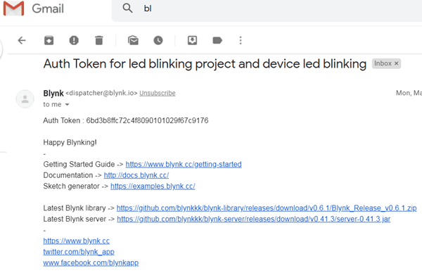
Enter the Auth Token in the code, which you can get from the Blynk App or from the mail you have received from Blynk.
char auth[ ] = "YourAuthToken";
To connect with WIFI enter your SSID name and password
char ssid[ ] = "YourNetworkName";
char pass[ ] = "YourPassword";
Here, void blinkLedWidget() function is used for switching ON and OFF the LED.
void blinkLedWidget()
{
  if (led1.getValue()) {
    led1.off();
    Serial.println("LED on V1: off");
  } else {
    led1.on();
    Serial.println("LED on V1: on");
  }
}
In void setup( ) function, we will initialize the baud rate, LED output and will connect the module with the Wi-Fi using Blynk.begin(auth,ssid,password); function. This function begins the Wi-Fi connection.
void setup()
{
  Serial.begin(9600);
  Blynk.begin(auth, ssid, pass);
  timer.setInterval(1000L, blinkLedWidget);
}
Testing LED Control using Blynk App and ESP32
Now, copy and paste the complete code into Arduino IDE. Then upload the code into the ESP8266.
Then, open the Blynk App for controlling the LED from the button widget.
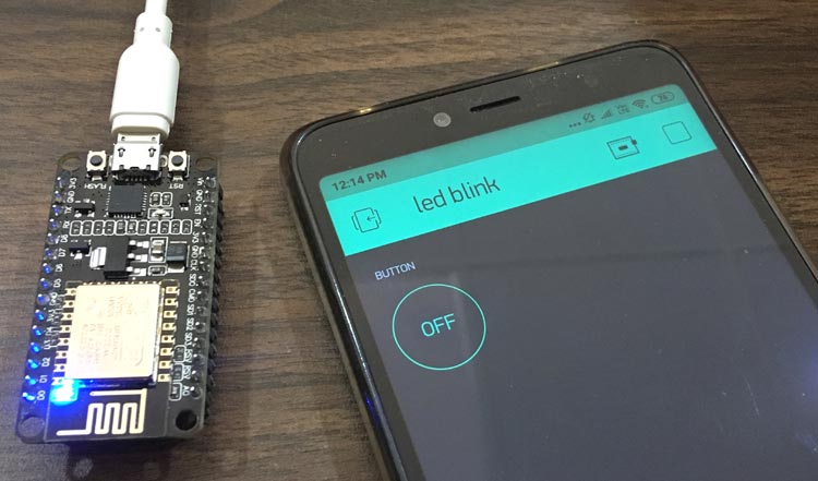
So we have successfully designed the Blynk App dashboard and controlled the LED through Blynk app using ESP8266.
Now in programming, first we need to include the libraries
#define BLYNK_PRINT Serial
#include <ESP8266WiFi.h>
#include <BlynkSimpleEsp8266.h>
// You should get Auth Token in the Blynk App.
// Go to the Project Settings (nut icon).
char auth[ ] = "YourAuthToken";
// Your WiFi credentials.
// Set password to "" for open networks.
char ssid[ ] = "YourNetworkName";
char pass[ ] = "YourPassword";
WidgetLED led1(V1);
BlynkTimer timer;
// V1 LED Widget is blinking
void blinkLedWidget() // function for switching off and on LED
{
if (led1.getValue()) {
led1.off();
Serial.println("LED on V1: off");
} else {
led1.on();
Serial.println("LED on V1: on");
}
}
void setup()
{
Serial.begin(9600);
Blynk.begin(auth, ssid, pass);
timer.setInterval(1000L, blinkLedWidget);
}
//In the loop function include Blynk.run() command.
void loop()
{
Blynk.run();
timer.run();
}


